Digital inputs
Pigeon computer RB700 has 8 digital opto-isolated inputs and 4 dry contact inputs.
Digital optoisolated inputs
8 digital opto-isolated inputs are divided into two sections. See picture below.
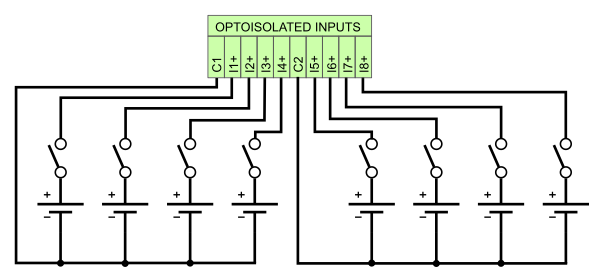
Fig. 1. Digital opto-isolated inputs connection
The following table shows the assignment between the opto-isolated inputs and the GPIO.
Table 1. Digital opto-isolated inputs
| INPUTS | GPIOD | GPIO SYSFS | GPIO SYSFS kernel below 6.6 |
|---|---|---|---|
| I1 | gpiochip2 8 | GPIO586 | GPIO496 |
| I2 | gpiochip2 9 | GPIO587 | GPIO497 |
| I3 | gpiochip2 10 | GPIO588 | GPIO498 |
| I4 | gpiochip2 11 | GPIO589 | GPIO499 |
| I5 | gpiochip2 12 | GPIO590 | GPIO500 |
| I6 | gpiochip2 13 | GPIO591 | GPIO501 |
| I7 | gpiochip2 14 | GPIO592 | GPIO502 |
| I8 | gpiochip2 15 | GPIO593 | GPIO503 |
When the input voltage is in the range of 0 - 5V, the logic state of the GPIO is one (negative logic). When the input voltage is in the range of 10 - 28 V, the state of GPIO is zero.
Table 2. Digital opto-isolated inputs parameters
| PARAMETER | VALUE |
|---|---|
| Quantity of inputs | 8 |
| Low-level input voltage | 0 ... +5 V DC |
| High-level input voltage | +10 ... +28V DC |
| Isolation voltage | 5 kV RMS |
| Input resistance | >=10kOhm |
Dry contact inputs
The following table shows the assignment between the dry contact inputs and the GPIO.
Table 3. Dry contact inputs
| INPUTS | GPIOD | GPIO SYSFS | GPIO SYSFS kernel below 6.6 |
|---|---|---|---|
| ID1 | gpiochip0 12 | GPIO590 | GPIO12 |
| ID2 | gpiochip0 13 | GPIO591 | GPIO13 |
| ID3 | gpiochip0 16 | GPIO594 | GPIO16 |
| ID4 | gpiochip0 17 | GPIO595 | GPIO17 |
When the input is shorted to GND, the logic state of the GPIO is one. Otherwise, the state of GPIO is zero.
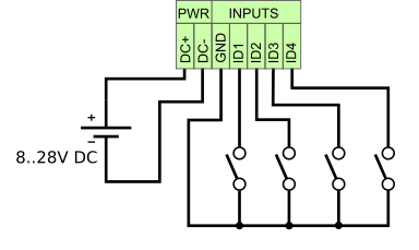
Fig. 2. Dry contact inputs connection
Linux kernel GPIO user space interface
gpiod
Installation of the gpiod tools:
apt install gpiodRead input I1 state:
gpioget gpiochip2 8Read input ID1 state:
gpioget gpiochip0 12GPIO Sysfs Interface for Userspace
Read input I1 state:
echo "586" > /sys/class/gpio/export
cat /sys/class/gpio/gpio586/value
1
echo "586" > /sys/class/gpio/unexport
Read input ID1 state:
echo "590" > /sys/class/gpio/export
cat /sys/class/gpio/gpio590/value
1
echo "590" > /sys/class/gpio/unexport
Direct control via the I2C interface
If you want to control the optoisolated inputs directly via the I2C interface, you need to comment out the following line in the /boot/firmware/config.txt file (or /boot/config.txt in older distributions):
dtoverlay=mcp23017,addr=0x20,gpiopin=23Otherwise, you will receive the message:
Error: Could not set address to 0x20: Device or resource busy.Reading input I1:
gpio -x mcp23017:100:0x20 read 108Information for Codesys Users
If you want to use binary inputs/outputs in Codesys, you need to comment out the following line in the /boot/firmware/config.txt file (or /boot/config.txt for older distributions):
dtoverlay=mcp23017,addr=0x20,gpiopin=23