Digital inputs
Pigeon computers are equipped with 8 digital opto-isolated inputs and 4 dry contact inputs.
Digital opto-isolated inputs
The 8 digital opto-isolated inputs are divided into two sections. See the picture below.
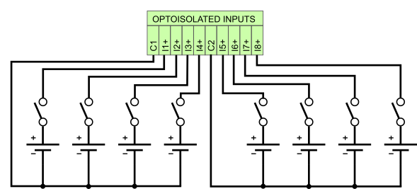
Fig. 1. Digital opto-isolated inputs connection
The following table shows the assignment between the opto-isolated inputs and the GPIO.
Table 1. Digital opto-isolated inputs - GPIO
| INPUTS | GPIO |
|---|---|
| I1 | GPIO12 |
| I2 | GPIO13 |
| I3 | GPIO18 |
| I4 | GPIO19 |
| I5 | GPIO20 |
| I6 | GPIO21 |
| I7 | GPIO22 |
| I8 | GPIO23 |
When the input voltage is in the range of 0 - 5V, the logic state of the GPIO is one (negative logic). When the input voltage is in the range of 10 - 28 V, the state of GPIO is zero.
Table 2. Digital opto-isolated inputs parameters
| PARAMETER | VALUE |
|---|---|
| Quantity of inputs | 8 |
| Low-level input voltage | 0 ... +5 V DC |
| High-level input voltage | +10 ... +28V DC |
| Isolation voltage | 5 kV RMS |
| Input resistance | >=10kOhm |
Dry contact inputs
The following table shows the assignment between the dry contact inputs and the GPIO.
Table 3. Dry contact inputs - GPIO
| INPUTS | GPIO |
|---|---|
| ID1 | GPIO30 |
| ID2 | GPIO31 |
| ID3 | GPIO32 |
| ID4 | GPIO33 |
When the input is shorted to GND, the logic state of the GPIO is one. Otherwise, the state of GPIO is zero.
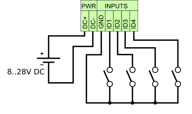
Fig. 2. Dry contact inputs connection
Software
Bash
Read input I1 (GPIO12) state:
echo "12" > /sys/class/gpio/export
cat /sys/class/gpio/gpio12/value
echo "12" > /sys/class/gpio/unexport
Example script which prints state of all digital inputs - read-all-binary-inputs.sh.
wget https://gitlab.com/pigeoncomputers/pigeon-rb-examples/-/raw/master/bash/read-all-binary-inputs.sh
chmod u+x read-all-binary-inputs.sh
./read-all-binary-inputs.sh
The WiringPi library is installed by default. WiringPi comes with a separate program to help manage the GPIO. Read input I1 (GPIO12) state with gpio program:
gpio -g read 12Python
Read input I1 (GPIO12) state:
python

>>> import RPi.GPIO as GPIO
>>> GPIO.setmode(GPIO.BCM)
>>> GPIO.setup(12, GPIO.IN)
>>> GPIO.input(12)
0